Tailings Dam Monitoring with InSAR & AI
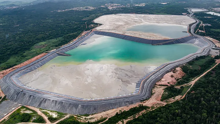
Tailings Dam Monitoring: How Advanced Satellite Intelligence Is Transforming Tailings Dam Safety Tailings dams are among the most critical—and high-risk—structures
Stereoscopic satellite imagery captures the same location from two different angles, allowing analysts to extract true 3D elevation data instead of just a flat map. By processing these image pairs, advanced photogrammetry generates accurate Digital Elevation Models (DEMs) for terrain evaluation, engineering, and environmental planning. This technology helps industries measure elevation, detect change over time, and model landscapes without physical site visits. XRTech Group delivers stereoscopic acquisition, processing, and DEM extraction for mining, infrastructure, agriculture, and high-precision land development projects.
What Stereo Imagery Does: Captures the same location from multiple angles to reveal height, elevation, and 3D terrain structure that standard monoscopic images cannot show.
How It Works: Agile optical satellites and SAR systems collect stereo or tri-stereo image pairs, which are processed using photogrammetry to calculate precise elevation values.
Key Outputs: Stereo data produces DEMs, DSMs, DTMs, point clouds, 3D city models, and Digital Twins with engineering-grade vertical accuracy (±3m RMSE).
Two Delivery Types:
Strip DEMs: Timestamped elevation layers for site-specific and change detection tasks.
Mosaic DEMs: Seamless, large-area datasets for regional planning, infrastructure, and government mapping.
Industry Value: Used across mining, construction, urban planning, hydrology, coastal management, telecom, agriculture, defense, and disaster response for informed operational decisions.
Why XRTech Group: Access to 130+ optical and SAR satellites, archive and new tasking options, DEM extraction support, and tailored 3D modeling services for every project size.
XRTech Group converts stereo imagery into measurable, reliable 3D intelligence for real-world planning, engineering, and development.
Monoscopic & Stereoscopic collections are the two primary methods of acquiring satellite imagery. They differ in their ability to perceive depth and generate three-dimensional data. While monoscopic imagery provides a standard two-dimensional view, stereoscopic collection uses multiple viewing angles to calculate height, elevation, and terrain structure.
Monoscopic collection is the most common form of satellite imaging and involves capturing a single image of a specific area from a nadir (directly overhead) or near-nadir perspective.
Primary Use Cases: Ideal for visual identification, tracking historical changes, creating base maps for urban planning, and monitoring real-time land use.
Data Characteristics: Mono imagery is delivered in standard processing levels (such as 1B, 2A, or 2D) and is typically the most cost-effective pricing tier.
Limitations: Mono imagery shows the horizontal footprint of objects but cannot accurately determine height or vertical displacement of structures, terrain, or landscape variation.
Stereoscopic collection acquires a pair of images of the same location from two different angles during the same satellite pass. In advanced missions, Tri-Stereo collection uses a third capture to enhance elevation accuracy in challenging terrain or dense urban environments.
3D Modeling Foundations: Stereo data is the basis for creating Digital Elevation Models (DEMs), Digital Surface Models (DSMs), and high-resolution 3D City Models.
Technical Process: Using a homonymous contour pairing algorithm, photogrammetric software analyzes the visual differences between stereo pairs to match corresponding pixels. The process performs building elevation correction and adjusts geographic coordinates to achieve maximum overlap, producing accurate building height and true topographic elevation.

Satellites capture stereo pairs by acquiring two or more images of the same geographic location from different viewing angles during a single orbital pass. This method mimics human depth perception, enabling the extraction of three-dimensional information to generate products like Digital Elevation Models (DEMs) and 3D city models.
Stereo acquisition depends on satellite agility, multi-angle imaging hardware, and precise viewpoint adjustments during orbit:
Multi-Angle Viewing: Satellites such as ZY-3 use three optical cameras—forward-viewing, backward-viewing, and nadir (directly overhead). Combining these viewpoints forms consistent stereo pairs for 3D elevation extraction.
Satellite Agility: Agile satellites like SuperView-1 and SuperView-2 (GFDM) use advanced attitude control to tilt mid-orbit, capturing the same target from different angles (e.g., 30° or 47°) to calculate topographic depth.
Dual-Linear Sensors: GF-7 employs a dual-linear CCD camera with a laser altimeter to collect sub-meter stereo data. The altimeter significantly enhances elevation accuracy, particularly in rugged or uneven terrain.
Once the “left” and “right” images are captured, they are processed to extract elevation detail:
Homonymous Contour Pairing: AI-driven photogrammetric algorithms match corresponding pixel contours between both images for consistency.
Elevation Correction: The system aligns building polygons and terrain features until maximum overlap is achieved. The point of maximum alignment is recorded as the accurate building-top or terrain elevation.
Tri-Stereo Imaging: In advanced missions, a third image is captured to improve accuracy in complex environments like narrow valleys, steep slopes, or dense urban “canyon” structures.
Stereo pairs are the foundation of high-value geospatial data products:
3D Geographic Scenes: Converting flat imagery into realistic 3D digital models for online mapping and virtual city environments.
InSAR-Based Elevation Models: Synthetic Aperture Radar (SAR) missions like LT-1 use dual-satellite formations for interferometry, delivering global DEMs and deformation monitoring with millimeter-level accuracy.
Cross-track stereo collection (often called left-right vision remote sensing) is a method of acquiring stereoscopic image pairs by capturing the same geographic area from different orbital positions or by tilting the satellite sideways. Unlike in-track stereo, where forward and backward images are taken seconds apart during a single pass, cross-track stereo collects imagery from separate orbital viewpoints. This wider geometric separation creates stronger parallax for height extraction, enabling highly accurate elevation modeling.
Cross-track stereo relies on advanced satellite agility and roll-angle adjustments to reposition the sensor mid-orbit:
Agile Attitude Control: Satellites like SuperView-2 (GFDM), SuperView Neo-1, and WorldView-3 use high-response control systems to tilt laterally and collect stereo views from different scanning directions.
Off-Nadir Viewing Angles: Typical roll angles between ±30° to ±45° produce the baseline separation required for calculating height, structure displacement, and elevation change.
Longer Baseline for Higher Accuracy: Because the viewing positions are farther apart than in-track stereo, the parallax effect is stronger, improving vertical accuracy—especially for tall buildings, mountainous terrain, and mining deformation analysis.
Multi-Sensor Enhancements: XRTech integrates optical stereo imagery with SAR (Synthetic Aperture Radar) interferometry to maintain 3D accuracy in cloudy, low-light, or obstructed environments.
Once the left and right images are captured, automated photogrammetric workflows extract elevation values:
Homonymous Contour Pairing: AI algorithms match corresponding pixels and building contours between image pairs to confirm geometric consistency.
Elevation & Polygon Correction: The system aligns building footprints across both images until maximum overlap is achieved, identifying the correct roof height and feature geometry.
Regularization & Model Smoothing: Building edges and terrain breaklines are simplified to remove distortion, producing clean digital 3D forms suitable for engineering use.
Improved Temporal Stability: Compared to in-track stereo (45–90 second separation), cross-track pairs may be captured hours apart, so automated correction handles shadow shifts, object displacement, and atmospheric changes.
Cross-track stereo supports the creation of advanced geospatial datasets for professional survey workflows:
Spatial Resolution:
• 0.30m SuperView Neo-1 (premium)
• 0.42m SuperView-2 (engineering standard)
• 0.50m SuperView-1 (general planning)
Primary Deliverables:
• Digital Elevation Model (DEM) – bare-earth elevation
• Digital Surface Model (DSM) – surface structures + vegetation
• Digital Terrain Model (DTM) – corrected 3D terrain with breaklines
• 3D city models, cadastral maps, slope & deformation analysis, and volumetric calculations
Accuracy Benchmarks:
• Horizontal Accuracy: Sub-meter level
• Vertical Accuracy: ±3m RMSE (engineering grade)
• Ground Spacing: 2–10m elevation grid spacing depending on terrain type
| Feature | In-Track Stereo | Cross-Track Stereo |
|---|---|---|
| Capture Timing | Same pass, seconds apart | Different pass or angled capture |
| Baseline Separation | Short | Larger → Higher vertical accuracy |
| Best For | Change detection, stability | 3D city modeling, elevation extraction |
| Environmental Limitations | Sensitive to motion/atmosphere | Stronger geometry, better for complex terrain |
XRTech Group leverages a specialized constellation of more than 130 optical and SAR satellites designed for stereoscopic data capture, 3D terrain modeling, and engineering-grade elevation products. These satellites acquire imagery from multiple viewing angles to calculate height, allowing the creation of high-precision datasets such as Digital Elevation Models (DEMs), Digital Surface Models (DSMs), Digital Terrain Models (DTMs), and 3D city models.
GF-7: China’s first sub-meter stereo mapping satellite, equipped with a dual-linear CCD camera and laser altimeter to enhance vertical accuracy in rugged terrain. It provides ~0.65m resolution stereo imagery and supports 1:10,000 scale topographic mapping.
ZY-3 Constellation: China’s primary civilian stereoscopic mapping system. It operates with three synchronized panchromatic cameras—forward, backward, and nadir—to create seamless stereo pairs. It supports 1:50,000 scale elevation databases with a nadir resolution of 2.1m.
These platforms provide multi-angle stereo acquisition through high-speed attitude control:
SuperView Neo-1: Offers 0.30m resolution and includes specialized stereo imaging modes for city-scale 3D modeling.
SuperView-2 (GFDM): A 0.42m VHR optical satellite capable of collecting standard stereo (30°–47°) and tri-stereo for enhanced accuracy in urban or mountainous environments.
SuperView-1: A four-satellite constellation with 0.5m resolution designed for large-area stereo mapping and elevation extraction workflows.
LT-1 Constellation: The world’s first dual-satellite L-band SAR formation designed for surface deformation monitoring and interferometry. LT-1A and LT-1B collect global DEM data at 1:50,000 scale, maintaining visibility in cloudy, rainy, or low-light conditions where optical sensors cannot operate. It can detect micro-movements with millimeter-level precision.
Stereo-capable satellites enable XRTech to provide engineering-grade geospatial intelligence:
Topographic Models: DEM (bare-earth), DSM (surface features), DTM (corrected terrain with breaklines)
Accuracy Standards:
• Ground spacing: 2–10m
• Vertical accuracy: ±3m RMSE (engineering grade)
Digital Twins & Smart Cities: 3D urban models with AI-based building contour extraction for planning and scenario simulation
Orthorectification Support: Stereo enables pixel-level geometric correction for alignment with real-world coordinates
The pricing for Stereoscopic (Stereo) and Tri-Stereoscopic (Tri-Stereo) satellite imagery is calculated as a multiplier of the base Monoscopic (Mono) imagery cost. Since stereo collection requires two or three viewing angles of the same target, the price reflects the added acquisition time, geometric requirements, and processing workload.
Standard global pricing multipliers applied across all XRTech satellite partners:
Stereo Imagery: 2× the Mono imagery cost
Tri-Stereo Imagery: 3× the Mono imagery cost
These rates apply to Optical Stereo data at standard processing levels (Level 1B and 2A).
Certain technical conditions may increase pricing depending on customer requirements:
| Condition | Adjustment |
|---|---|
| 8-Band Multispectral (PAN + 8MS) | +10% uplift |
| Guaranteed Cloud Cover ≤ 5% | +$8 / km² |
| Off-Nadir Angle ≤ 15° (better elevation accuracy) | +$3 / km² |
| Off-Nadir Angle ≤ 10° (premium accuracy) | +$9 / km² |
| Resolution Tier | Minimum Area |
|---|---|
| 30cm & 50cm Stereo | 25 km² (Archive) / 100 km² (New Tasking) |
| Strip / Linear AOIs | Must exceed 5 km width
|
Purchasing Stereo imagery is like buying two synchronized views of the same location. This dual-angle capture allows software to calculate depth, elevation, and surface structure. Because the satellite must retarget and collect additional geometric data, the pricing represents the extra collection effort and processing needed to convert a flat Mono image into a 3D-ready dataset.

The transformation of two flat satellite images into a 3D elevation model is achieved through stereoscopic (stereo) collection and photogrammetry. This method captures the same geographic location from two or more viewing angles during a single satellite pass and then uses geometric disparity to calculate height. This is the foundation for generating Digital Elevation Models (DEM), Digital Surface Models (DSM), and architectural-grade 3D models.
Agile satellites such as SuperView Neo-1, GF-7, and ZY-3 tilt their sensors to capture the same area from different angles—commonly 30° or 47° between images. These angles create the necessary parallax to calculate height and terrain depth.
Photogrammetric algorithms identify corresponding features between the left and right images. Instead of matching only key landmarks, stereo DEM extraction attempts to match every pixel to its counterpart in the second image.
Because each pixel shifts slightly between angles, this positional difference (disparity) becomes the primary source of elevation measurement.
Objects with height—such as buildings, cliffs, or elevated terrain—appear in different pixel positions between the two images. The greater the displacement, the higher the object stands above the reference ground.
Elevation accuracy depends on:
Viewing angle separation (convergence angle)
Satellite altitude during capture
Sensor calibration and geolocation accuracy
Precise GPS and satellite telemetry record the satellite’s position at the time of capture. With disparity measured, the system performs triangulation to calculate each point’s real position:
X, Y → Horizontal location
Z → Elevation value (height)
This step produces a dense point cloud containing millions of accurately positioned elevation points.
The point cloud is interpolated into a raster grid to generate elevation products:
DEM (bare-earth terrain)
DSM (buildings, vegetation, infrastructure)
DTM (terrain with breaklines for engineering)
Every pixel in the stereo-derived DEM represents the real elevation at that exact location.
| Product | What It Represents | Primary Use Case |
|---|---|---|
| DEM (Digital Elevation Model) | Bare-earth terrain with all structures removed | Hydrology, land planning, engineering |
| DSM (Digital Surface Model) | Top of buildings, trees, infrastructure | Urban design, telecom planning, forestry |
| 3D White Models | Simplified architectural building forms | 3D city modeling, simulation, visualization |
Satellites like GF-7 improve vertical accuracy using:
Dual-linear CCD camera for stereo capture
Laser altimeter for altimetric referencing
AI elevation correction and regularization
This enables XRTech Group to deliver:
±3m RMSE vertical accuracy
2–10m spacing resolution suitable for engineering, hydrology, and infrastructure planning.
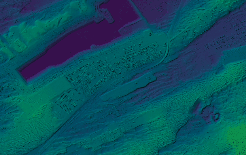
In geospatial intelligence, Digital Elevation Models (DEMs) are categorized based on how they are captured and processed. Strip DEMs are created from a single stereo satellite pass, while Mosaic DEMs are stitched, processed composites built from multiple strips to form larger regional or national datasets.
Strip DEMs are derived from a single orbital pass, produced when agile satellites like SuperView-1, SuperView Neo-1, or ZY-3 collect stereo pairs in “long-strip” or “stereo acquisition” mode. A typical strip measures 15–17 km wide and 15–100 km long, matching the natural coverage of the source imagery.
The defining characteristic of Strip DEMs is their timestamped accuracy. Because both images are captured within seconds of each other, the resulting elevation model represents the terrain exactly as it existed at that moment in time.
Key Characteristics
Acquisition: Generated from optical stereo image pairs captured from different viewing angles, enabling height extraction through parallax.
Coverage: Ideal for precise mapping of a specific Area of Interest (AOI). For example, a SuperView Neo target strip may span up to 60 km × 90 km.
Speed: Faster delivery and reduced processing make Strip DEMs suitable for urgent monitoring—often deployable within 24 hours in emergency scenarios.
Best For
Mining: Volumetric change in stockpiles, pits, and waste dumps
Landslide analysis: Terrain displacement and hazard evaluation
Coastal erosion: Beach, dune, and shoreline retreat monitoring
Construction progress: Earthworks validation and site preparation
Collecting multiple stereo strips over time allows the creation of temporal elevation datasets to analyze terrain evolution and support long-term decision-making.
Mosaic DEMs are produced by co-registering, aligning, and blending multiple Strip DEMs to remove edge inconsistencies. The result is a seamless elevation layer covering regions, states, or entire countries.
However, Mosaic DEMs are not timestamp-uniform. Since the source strips may be captured months or years apart, different areas within the mosaic reflect terrain conditions from different dates.
Key Characteristics
Processing: Involves advanced fusion, blending, block adjustment, and spatial alignment to eliminate seams and elevation jumps between strips.
Consistency: Designed to function as a continuous elevation dataset with unified geometry and color balance across large areas.
Output: Considered the “value-added” standard for GIS infrastructure, Smart City planning, and national geospatial programs.
Best For
Regional planning and infrastructure routing
Watershed analysis and flood risk modeling
Agricultural drainage and irrigation design
Baseline datasets for government and urban management
National Digital Twin models for smart governance
| Feature | Strip DEM | Mosaic DEM |
|---|---|---|
| Source | Single stereo satellite pass | Multiple strips stitched together |
| Scale | Targeted (e.g., 60km × 90km) | Regional, national, continental |
| Timestamp | Single timestamp (event-specific) | Multi-date composite |
| Consistency | High accuracy within strip; visible edges possible | Seamless, block-adjusted, uniform |
| Processing Level | Orthorectification + parallax extraction | Fusion, mosaicking, block adjustment |
| Primary Use | Engineering, mining, emergency response | Urban planning, GIS base maps, Smart Cities |
Mining / Engineering: Strip DEMs for feasibility studies and short-term monitoring in remote zones.
Urban Management / Smart Cities: Mosaic DEMs for monitoring development, zoning compliance, and infrastructure expansion.
Government & National GIS: Mosaic DEMs form the foundational layer for Digital Twins and multi-city elevation management.
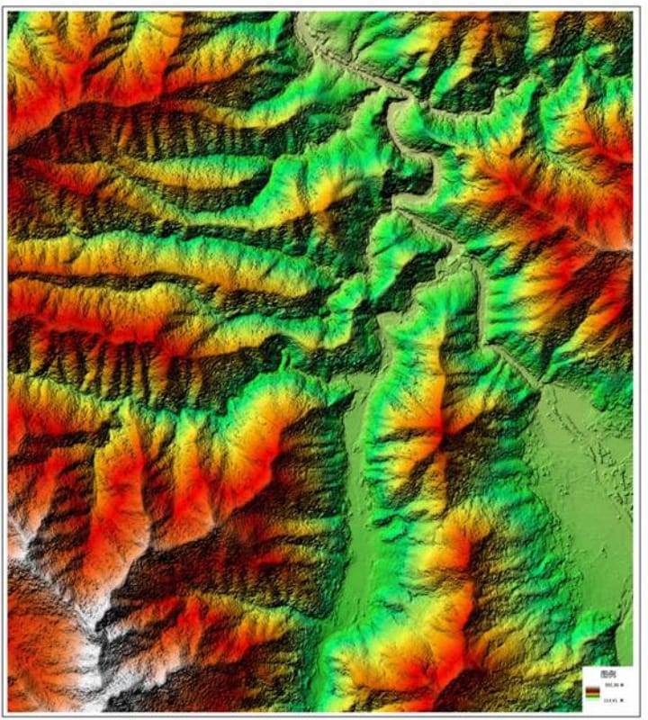
Stereoscopic satellite imagery and the 3D elevation products derived from it—such as Digital Elevation Models (DEMs) and Digital Surface Models (DSMs)—play a crucial role across multiple industries that depend on precision terrain and infrastructure data. By capturing scenes from multiple viewing angles, stereo collection provides engineering-grade vertical accuracy (often ±3m RMSE), enabling confident planning, assessment, and decision-making at scale.
Stereo-derived 3D data supports modern urban development, zoning, and digital governance.
Digital Twins & 3D City Models: Elevation data is used to build accurate 3D replicas of real-world environments.
Building White Models: AI extracts building footprints and heights to create simplified 3D “box models” for planning and visualization.
Zoning, Expansion & Compliance: Helps detect unauthorized construction, monitor urban sprawl, and conduct scenario modeling for sustainable growth.
Stereo imagery improves engineering workflows by replacing slower and riskier traditional field surveys.
Route Optimization: DTMs guide road, rail, and pipeline alignment by analyzing slope, grade, and terrain constraints.
Volumetric Calculations: DEMs calculate cut-and-fill volumes for accurate earthwork planning and cost control.
Infrastructure Validation: Used for as-built verification, corridor planning, drainage, and flood-risk modeling.
Stereo provides essential “terrain intelligence” from early exploration to active mining operations.
Exploration Mapping: 3D terrain and geological models help identify shear zones, fault lines, and target mineral deposits.
Operational Efficiency: Supports drill planning, haul road design, and evaluation of overburden volumes.
Risk Monitoring: Stereo + SAR fusion detects deformation in tailings dams, pits, and pipelines to prevent structural failures.
Stereo captures elevation and depth variations where standard 2D imagery falls short.
Port & Harbor Planning: Coastal DSMs provide 3D insight into port infrastructure, shoreline constraints, and expansion risk.
Coastal Erosion Tracking: Repeated stereo mapping reveals shoreline change, sediment shift, and vulnerability to sea-level rise.
Elevation data is central to modeling how water interacts with terrain.
Flood Modeling & Watershed Analysis: DEMs predict drainage behavior, flood corridors, and hazard zones.
Environmental Impact Assessment: Used for slope stability, erosion prediction, and rehabilitation planning.
Ecosystem Monitoring: Supports biomass estimation, canopy height modeling, and habitat risk assessments.
Stereo data enhances mission-critical planning and technical infrastructure modeling.
Military & Simulation: High-precision 3D terrain powers mission rehearsal systems, flight simulators, and tactical planning.
Telecom Signal Analysis: DSMs reveal obstruction points for wireless network design, antenna siting, and signal propagation modeling.
Stereo-informed elevation data improves land management and production forecasting.
Topography-Based Zoning: Field segmentation according to slope, soil flow, and irrigation behavior.
Drainage & Irrigation Engineering: Prevents waterlogging and optimizes system design.
Precision Planting: Terrain-based guidance increases yield and reduces input waste.
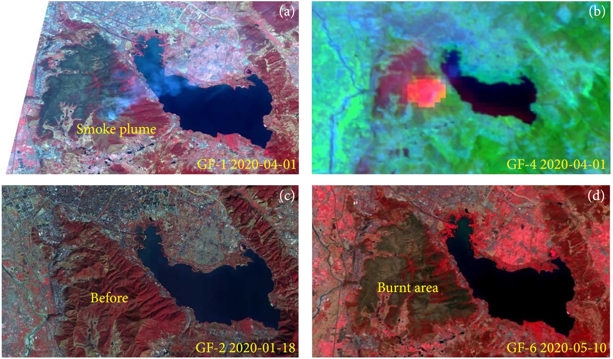
Stereo pairs enable rapid analysis before and after catastrophic events.
Before/after elevation change detection
Landslide, debris flow, and instability mapping
Flood extent and damage analysis
Infrastructure integrity assessment
XRTech Group provides access to stereoscopic satellite imagery from a global network of optical and SAR satellites, including archive data and new custom tasking options. This ensures that projects requiring elevation intelligence, 3D terrain modeling, and change detection can be completed with the most suitable data source available. Clients can request existing stereo pairs, schedule new collections, or receive full DEM processing support—from raw imagery to deliverable-ready 3D elevation products.
Existing stereo imagery can be sourced from our archive for locations worldwide. This option is ideal when budget and delivery speed are priorities.
Search by area of interest, sensor type, date, and cloud cover
Preview coverage footprints and technical specifications
Immediate download or server-side streaming options available
When archive data is unavailable or outdated, XRTech can coordinate new tasking orders for current stereo captures.
Collection feasibility and orbital availability analysis
Selection of sensors based on required accuracy and resolution
Priority and emergency tasking options for time-sensitive projects
If elevation output is required, XRTech provides complete stereo-to-DEM processing workflows.
DEM, DSM, and DTM generation for engineering-grade use
Orthorectified stereo pairs and georeferenced elevation grids
Quality assurance to meet vertical accuracy requirements (±3m RMSE)
| Product Type | Output |
|---|---|
| Raw Stereo Pairs | Left/Right image sets for in-house processing |
| Orthorectified Stereo | Radiometrically + geometrically corrected |
| DEM / DSM / DTM | Engineering-grade elevation models |
| 3D City Models | Building height and structure reconstruction |
| Time-Series Elevation | Change detection over multiple dates
|
Not sure which approach is right for your project? Contact us and we can assess your area of interest, accuracy requirements, and timeline to recommend the best data source—archive stereo, new tasking, or complete DEM processing.
Stereoscopic satellite imagery is transforming how organizations understand terrain, build infrastructure, and plan with confidence. By capturing the same location from multiple angles, stereo and tri-stereo collections unlock true 3D intelligence—elevation, structure height, and landscape change that standard 2D imagery cannot provide. Whether you need a single strip DEM for a project site or a full regional mosaic for long-term development, XRTech Group delivers data, processing, and expertise built around your accuracy requirements.
If you are exploring 3D mapping, elevation modeling, or terrain-based decision-making, XRTech Group provides end-to-end solutions—from archive checks to new tasking, DEM/DSM extraction, and Digital Twin integration.
Ready to move forward? Let’s plan your next project with precision.
Tailings Dam Monitoring: How Advanced Satellite Intelligence Is Transforming Tailings Dam Safety Tailings dams are among the most critical—and high-risk—structures

From Visible Light to Spectral Intelligence in Modern Satellite Remote Sensing Satellite imaging has moved beyond photography. For decades, Earth