Quick Answer:
CE90 (Circular Error 90%) is the radius within which 90% of measured points in a satellite image fall from their true ground position. A CE90 of 8m means 90% of all pixels in the image are within 8 metres of their actual location on Earth. The lower the CE90 value, the more positionally accurate the imagery. CE90 measures horizontal accuracy across the X and Y axes (latitude and longitude) and is the standard metric for evaluating how reliably satellite imagery aligns with real-world coordinates.
Intro
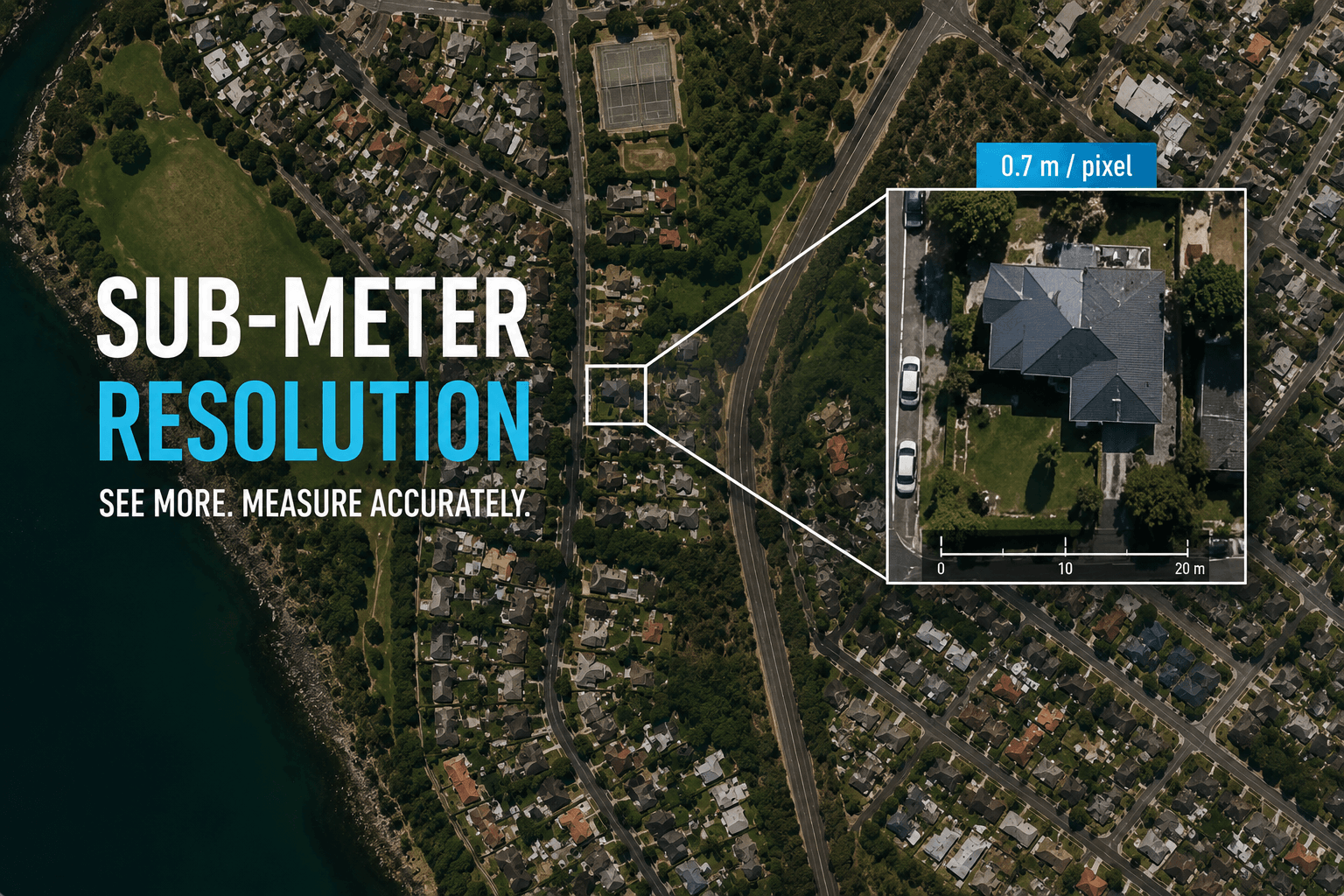
Positional accuracy is the factor most satellite data buyers overlook when ordering satellite imagery. Resolution tells you how sharp an image is. CE90 tells you how truthful it is. An image can show a road at 0.3m resolution and still place that road 15 metres from where it actually sits on the ground. For visual inspection, that error is invisible. For GIS overlay, infrastructure mapping, or regulatory compliance work, it is a serious problem.
What Is CE90?
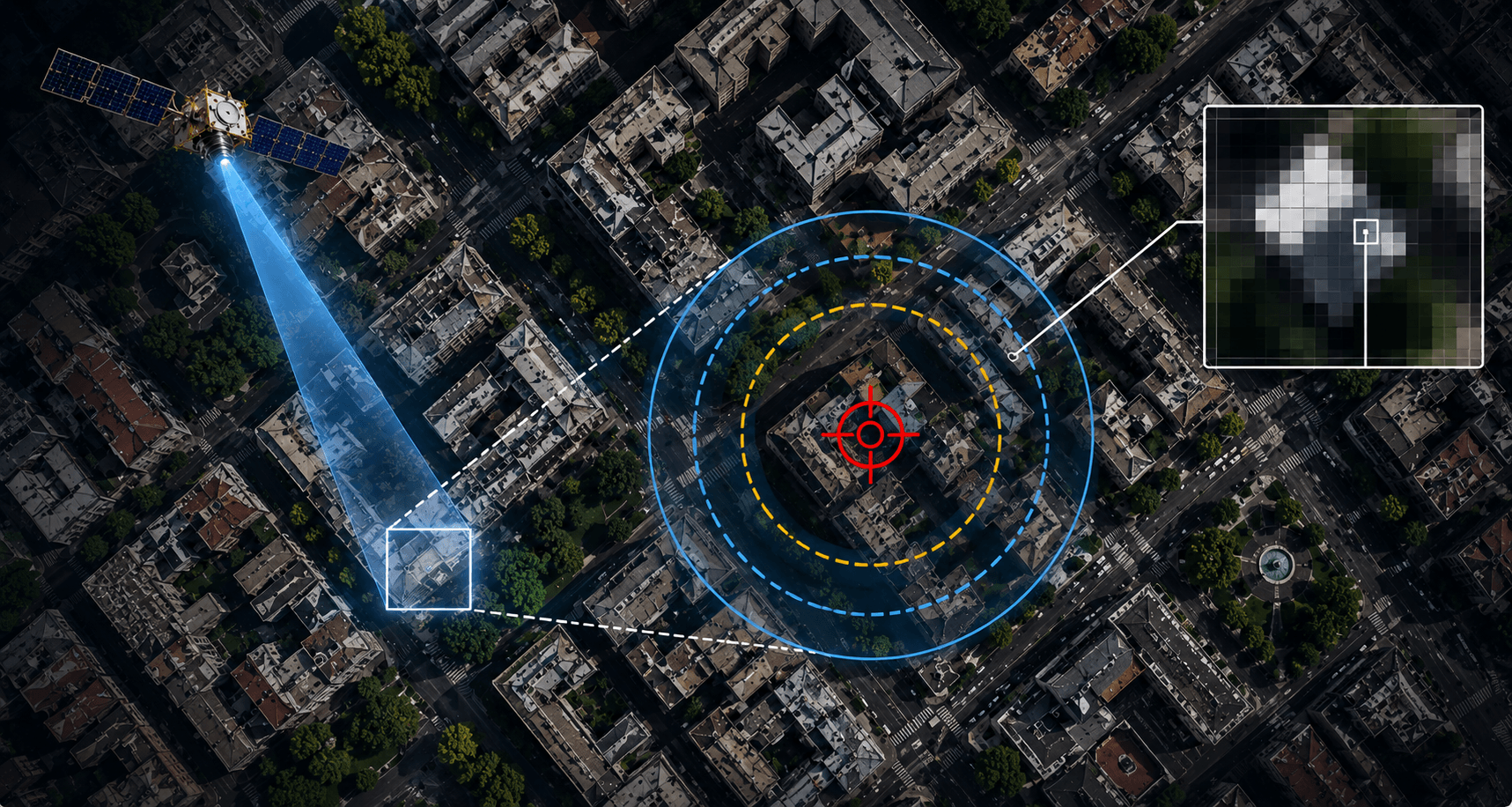
CE90 is a statistical measure of horizontal positional accuracy. It defines a circle around the true ground position of any point in an image. If a dataset has a CE90 of 8m, it means that 90% of all measured points in that dataset fall within an 8-metre radius of their true location.
The remaining 10% of points may fall outside that radius. CE90 does not mean every pixel is within 8 metres. It means 9 out of 10 are.
CE90 is measured on the horizontal plane only, covering the X axis (longitude) and Y axis (latitude). It has nothing to do with elevation. That is measured separately using RMSE.
CE90 vs RMSE: Horizontal vs Vertical Satellite Imagery Accuracy
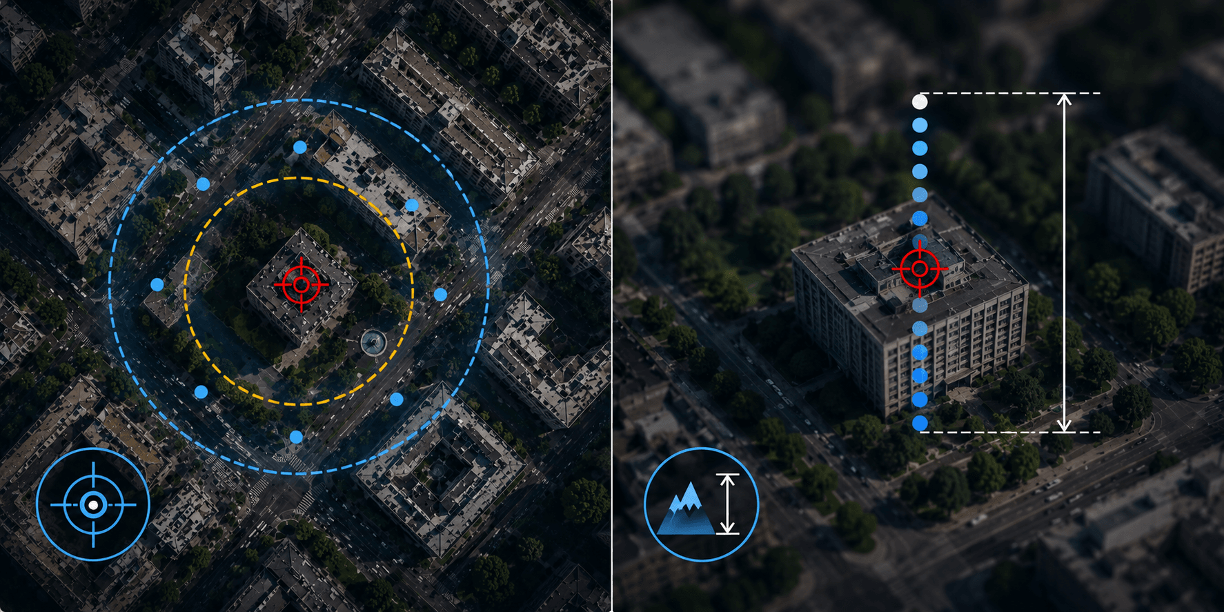
These two metrics are often mentioned together but they measure completely different things. Confusing them leads to ordering data that does not meet your project requirement.
| Feature | CE90 | RMSE |
|---|---|---|
| Full name | Circular Error 90% | Root Mean Square Error |
| Axis measured | X and Y (latitude, longitude) | Z (elevation, altitude) |
| What it describes | Horizontal positional accuracy | Vertical accuracy of elevation data |
| Standard product | Digital Orthophoto Map (DOM) | Digital Elevation Model (DEM) |
| XRTech standard | 8m CE90 | Plus or minus 3m RMSE |
| Used for | GIS overlays, road mapping, infrastructure | Hydrology, volume calculation, terrain modelling |
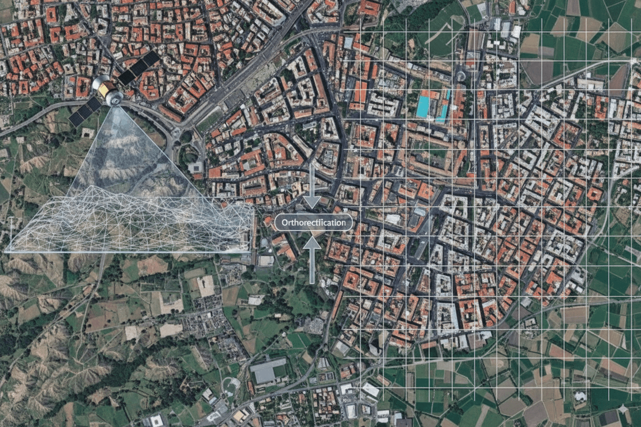
Both metrics are needed for full spatial accuracy. Orthorectification is the process that links them: it uses elevation data (RMSE from a DEM) to correct distortions in raw imagery, which then produces the correct horizontal position (CE90) across the full image extent.
How CE90 Is Calculated
CE90 is derived from the radial Root Mean Square Error (RMSEr), which measures the combined horizontal error across both X and Y axes. The conversion formula is:
CE90 = 1.5175 x RMSEr
Where RMSEr is calculated from a set of check points with known true coordinates. These check points are measured in the image and compared against their actual ground positions. The distribution of errors is used to compute RMSEr, and then CE90 is derived from that.
This formula assumes a normal distribution of errors. For most commercial satellite sensors under standard operating conditions, this assumption holds well.
What Affects CE90 in Satellite Imagery?
Several factors influence the CE90 value of a satellite image before and after delivery.
Off-Nadir Angle
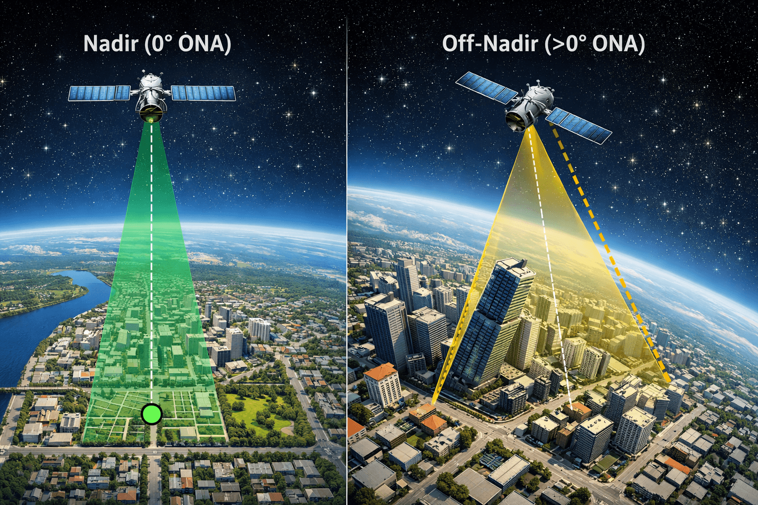
Nadir is the point directly below the satellite. When a satellite tilts to capture an image at an angle (off-nadir), each pixel covers a larger and less precisely defined area on the ground. The further off-nadir, the worse the CE90. For engineering-grade accuracy, request imagery captured at under 15 degrees off-nadir wherever possible.
Orbital Altitude

Lower orbital altitude reduces the distance between sensor and ground, which improves GSD and can improve CE90 if the sensor is well-calibrated. Most commercial VHR satellites operate at 400km to 600km altitude.
DEM Quality Used in Orthorectification
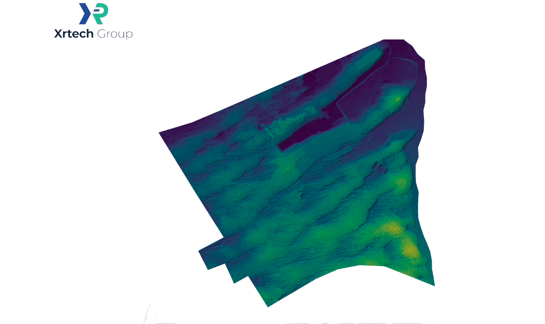
Orthorectification corrects terrain and viewing angle distortions using a Digital Elevation Model. If the DEM used in orthorectification is coarse or inaccurate, the resulting CE90 degrades. Higher quality DEMs, particularly from lidar or stereo mapping, produce better orthorectified CE90.
Ground Control Points (GCPs)
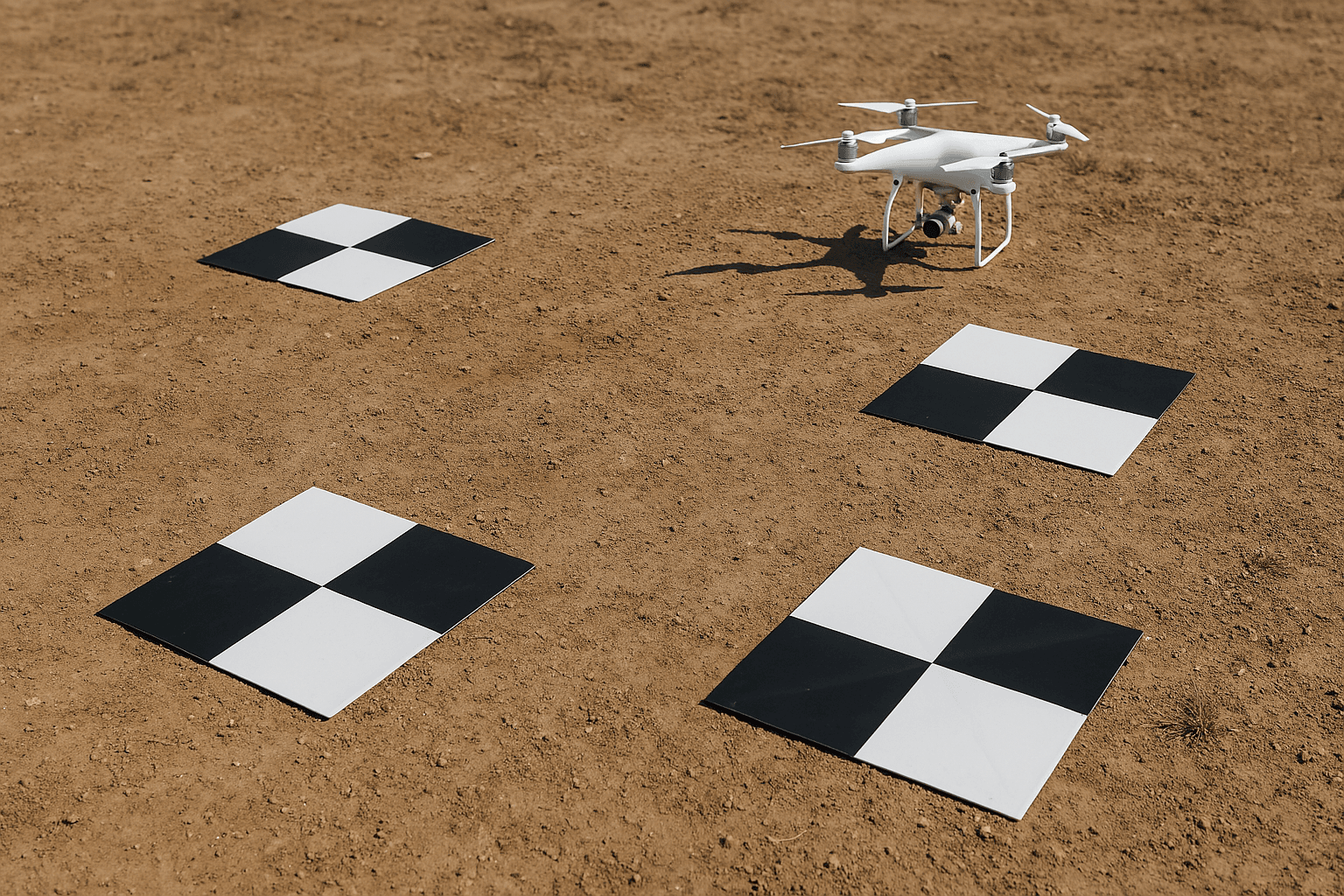
GCPs are surveyed reference points on the ground with precisely known coordinates. When used during image processing, GCPs constrain the image to match true ground positions. A standard orthorectified product without GCPs achieves 5m to 8m CE90. The same image processed with GCPs can reach sub-1m CE90 for engineering applications.
Sensor Calibration
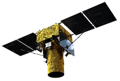
Each satellite sensor is calibrated in orbit. Better-calibrated sensors produce more consistent CE90 values across a dataset. XRTech satellites are calibrated against known ground reference networks and meet the accuracy specifications listed below.
CE90 Accuracy by Satellite: XRTech Fleet

XRTech provides access to over 130 satellites with a range of CE90 specifications across optical and radar sensors. Here is the positional accuracy data for key platforms.
Very High Resolution Optical
GF-7 is a standout for positional accuracy in the XRTech fleet. It carries a laser altimeter in addition to its stereo optical sensors. In plain terrain it achieves RMSE of 0.5m or better vertically and under 2m CE90 horizontally, making it eligible for 1:10,000 scale topographic mapping without GCPs.
Medium Resolution Optical
| Satellite | GSD | CE90 at Nadir |
|---|---|---|
| GF-6 | 2.0m | 15m to 20m CE90 |
| ZY-3 | 2.1m | 10m CE90 with stereo |
| GF-1 | 8.0m | 50m CE90 |
| GF-1 WFI | 16.0m | 50m CE90 |
Medium resolution satellites have wider CE90 values, which is acceptable for their primary use cases of regional monitoring, land cover mapping, and vegetation analysis where pixel-perfect positional alignment is not the priority.
SAR Satellites
SAR positional accuracy benefits from the same orthorectification process as optical imagery. Because SAR operates in all weather and at night, it is often the primary source for urgent mapping where optical cannot guarantee a clear capture, and its CE90 is sufficient for flood extent mapping, change detection, and infrastructure monitoring.
Standard Delivered Products
XRTech’s Digital Orthophoto Maps (DOM) are delivered with a consistent 8m CE90 across the full dataset. This is the standard horizontal accuracy specification for map-ready imagery products from the XRTech fleet and is sufficient for most GIS integration, urban planning, and infrastructure mapping workflows.
CE90 Compared Across Data Sources
Understanding where satellite CE90 fits relative to other data sources helps you determine whether satellite imagery alone meets your project requirement or whether supplementary data is needed.
| Data Source | Typical CE90 | Notes |
|---|---|---|
| Survey-grade drone with RTK/PPK | 2cm to 10cm | Best accuracy, limited area coverage |
| Aerial orthophotography (Nearmap) | 25cm to 30cm | Urban areas, limited global coverage |
| Commercial VHR satellite (SuperView Neo-1) | 2m to 4m | Global coverage, no field crew needed |
| Commercial VHR satellite (SuperView-1) | 5m to 8m | Standard commercial benchmark |
| Google Maps (urban areas) | Around 1m | Dense GCP network in cities |
| Google Maps (rural or mountainous) | 5m to 15m | Degrades with terrain complexity |
| Medium resolution satellite (GF-1) | 50m | Regional monitoring, not for precise mapping |
Drones achieve the finest CE90 but are limited to small areas and require physical mobilisation. Satellite imagery at 2m to 8m CE90 covers any location on Earth within 48 hours without a field crew. For projects covering more than a few hundred hectares, satellite imagery is the only practical option for consistent positional accuracy at scale.
Why CE90 Matters: Real Project Consequences
GIS Overlay and Vector Integration
When you overlay satellite imagery with existing GIS layers such as road networks, cadastral boundaries, or utility lines, the imagery CE90 must be compatible with the accuracy of those layers. If your GIS data has 2m accuracy and your imagery has 15m CE90, buildings and roads in the image will not align with the vector data. This produces false measurements and errors in any analysis built on top.
Infrastructure and Engineering
For construction layout, pipeline routing, and infrastructure inspection, positional accuracy directly affects whether the imagery can be used to make real decisions. A 0.3m GSD image with 5m CE90 shows a road in clear detail but places it 5 metres from its true position. If the engineering team is using that image to plan an adjacent structure, the 5-metre offset is a significant design error.
Regulatory Compliance
In oil and gas, mining, and urban development, regulations often specify minimum distances between infrastructure, protected zones, and property boundaries. Imagery used to verify compliance must have CE90 accurate enough to confirm those distances. If the CE90 is wider than the regulatory buffer, the imagery alone cannot confirm compliance and ground survey is required.
Disaster Response and Emergency Mapping
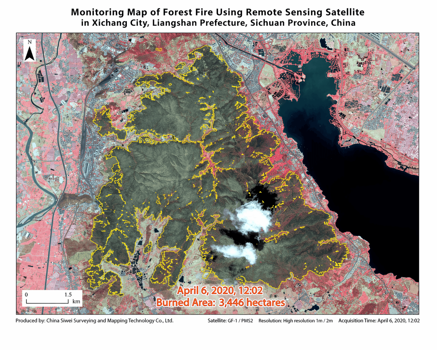
In flood or earthquake response, imagery is used to identify which roads are passable, which buildings are damaged, and where relief teams can access. A 5m to 8m CE90 is sufficient for this because the decisions being made are at a scale where metre-level precision is not critical. SAR imagery at 5m to 10m CE90 is regularly used for disaster mapping because it provides timely data regardless of cloud cover.
How to Improve CE90 After Delivery
If the standard CE90 of your delivered imagery does not meet your project requirements, there are two main options.
Ground Control Points (GCPs)
GCPs are surveyed points on the ground with precisely known coordinates, collected by GPS or total station. When applied to imagery during orthorectification, GCPs anchor the image to true ground positions and reduce CE90 significantly. A product delivered at 8m CE90 can reach 0.5m to 1m CE90 after GCP-based reprocessing.
The trade-off is that GCP collection requires field work in your AOI, which adds cost and time. For remote or inaccessible areas, this may not be feasible. In those cases, the native CE90 of the imagery is the practical limit.
Higher Quality DEM in Orthorectification
If orthorectification was performed using a coarse DEM, replacing it with a higher resolution DEM (such as GF-7 laser altimeter data at 0.5m RMSE) during reprocessing improves CE90 without requiring field GCPs. XRTech provides access to DEM data for this purpose.
CE90 and Preprocessing Level
CE90 values vary depending on the processing level of the delivered product.
| Processing Level | CE90 Expectation | Notes |
|---|---|---|
| Level 1A (raw) | Not applicable | No geometric correction applied |
| Level 2A (georeferenced) | 20m to 50m CE90 | Projected to map coordinates but terrain not corrected |
| Level 3 (orthorectified) | 5m to 15m CE90 | Standard delivered accuracy from XRTech |
| Level 3 with GCPs | Under 1m CE90 | Engineering grade, requires field survey |
Always confirm the preprocessing level and its associated CE90 specification before ordering. If your project requires sub-5m CE90 without GCPs, discuss this with XRTech before tasking so the right satellite and acquisition geometry can be selected.
Order Satellite Imagery With Certified CE90 Accuracy
Buy orthorectified satellite imagery with CE90 specifications certified for each product tier. Standard DOM products are delivered at 8m CE90. SuperView-1 achieves 5m to 8m CE90 at nadir. SuperView Neo-1 achieves 2m to 4m CE90, and GF-7 stereo with laser altimeter achieves under 2m CE90 for precision mapping applications.
Archive imagery starts at $1/km2. New tasking starts at $8/km2. All products are delivered with full metadata including CE90 specification, off-nadir angle, and acquisition date.
Contact XRTech with your AOI and accuracy requirement and we will confirm the right satellite, processing level, and CE90 specification for your project within 24 hours.
FAQs
What does CE90 mean in satellite imagery?
CE90 means Circular Error 90%. It is the radius within which 90% of measured points in a satellite image fall from their true ground position. A CE90 of 8m means 90% of all image pixels are within 8 metres of their actual location on Earth.
What is the difference between CE90 and RMSE?
CE90 measures horizontal positional accuracy across the X and Y axes (latitude and longitude). RMSE measures vertical accuracy along the Z axis (elevation). CE90 is used for map accuracy and GIS alignment. RMSE is used for Digital Elevation Models, terrain analysis, and volume calculations.
What CE90 does SuperView-1 achieve?
SuperView-1 achieves 5m to 8m CE90 at nadir under standard delivery conditions. This is the benchmark for most commercial VHR satellite imagery applications and is sufficient for GIS overlay, urban mapping, and infrastructure inspection.
Can CE90 be improved after delivery?
Yes. Applying Ground Control Points (GCPs) during reprocessing can reduce CE90 from 8m to under 1m. Using a higher quality DEM in orthorectification also improves CE90 without requiring field GCPs. XRTech supports both options on request.
How does off-nadir angle affect CE90?
Off-nadir capture increases the distance between sensor and target for any given pixel, which increases the positional uncertainty. The greater the off-nadir angle, the worse the CE90. For engineering or compliance work, request imagery at under 15 degrees off-nadir to protect positional accuracy.
What CE90 do I need for GIS overlay work?
This depends on the accuracy of your existing GIS layers. If your road network or cadastral data has 2m accuracy, your imagery CE90 should be close to that to avoid visible misalignment. For most urban GIS workflows, 5m to 8m CE90 is sufficient. For precision engineering overlay, under 2m CE90 with GCPs is recommended.
What is the CE90 of XRTech Digital Orthophoto Maps?
XRTech Digital Orthophoto Maps (DOM) are delivered at a consistent 8m CE90 across the full dataset. This is the standard for map-ready imagery from the XRTech fleet and meets the accuracy requirements for most GIS, planning, and infrastructure mapping workflows.
What is the most accurate satellite in the XRTech fleet for positional accuracy?
GF-7 achieves the best positional accuracy in the XRTech fleet for mapping applications. Its laser altimeter delivers under 0.5m RMSE vertically in plain terrain and under 2m CE90 horizontally, making it eligible for 1:10,000 scale topographic mapping. SuperView Neo-1 achieves 2m to 4m CE90 for general VHR imaging.
Does SAR imagery have CE90 specifications?
Yes. GF-3 SAR achieves 5m to 10m CE90 and LT-1 SAR achieves approximately 10m CE90 after standard orthorectification. SAR CE90 is sufficient for flood mapping, change detection, and infrastructure monitoring, and can be improved with GCPs in the same way as optical imagery.
How does CE90 relate to the scale of map I can produce?
Standard cartographic guidelines require that map accuracy at a given scale meets a CE90 of roughly 0.5mm x the map scale denominator. For a 1:10,000 map, that means 5m CE90. GF-7 with laser altimeter meets this without GCPs. For a 1:5,000 map, under 2.5m CE90 is needed, which requires GCPs with most other satellites.
Blog Summary
- CE90 stands for Circular Error 90% and measures horizontal positional accuracy in satellite imagery
- A CE90 of 8m means 90% of all image pixels are within 8 metres of their true geographic location
- CE90 measures accuracy on the X and Y axes (latitude and longitude), not elevation
- Vertical accuracy is measured separately using RMSE (Root Mean Square Error) on the Z axis
- SuperView-1 achieves 5m to 8m CE90 at nadir, one of the best specs in the XRTech fleet
- Orthorectification uses elevation data (RMSE) to correct terrain and angle distortions, which directly improves CE90
- Ground Control Points (GCPs) can improve CE90 from 8m down to under 1m after post-processing
- Off-nadir capture angles degrade CE90 because pixels cover more ground area as the sensor tilts
- CE90 is essential for GIS overlays, infrastructure mapping, and any project where pixel position must match a real coordinate
- XRTech Digital Orthophoto Maps (DOM) deliver a consistent 8m CE90 across the full dataset